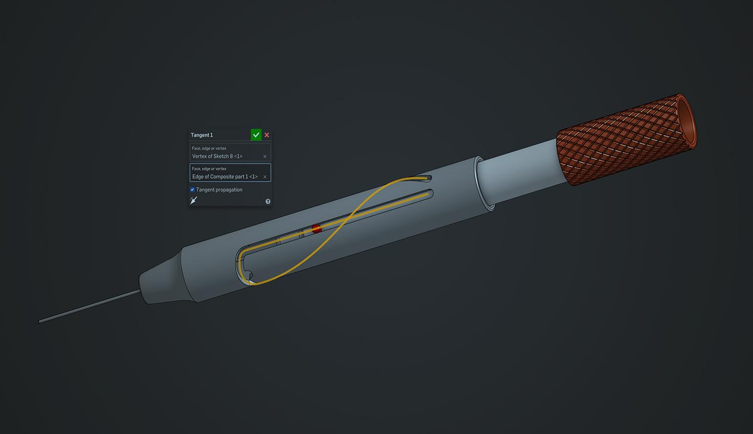
1:43
There are many mechanisms that incorporate a sliding motion, sometimes combined with a rotational movement of a pin. Most commonly, just a linear sliding motion can be achieved with Onshape’s Slider Mate or, if a rotating pin is required as well, with the Pin Slot Mate.
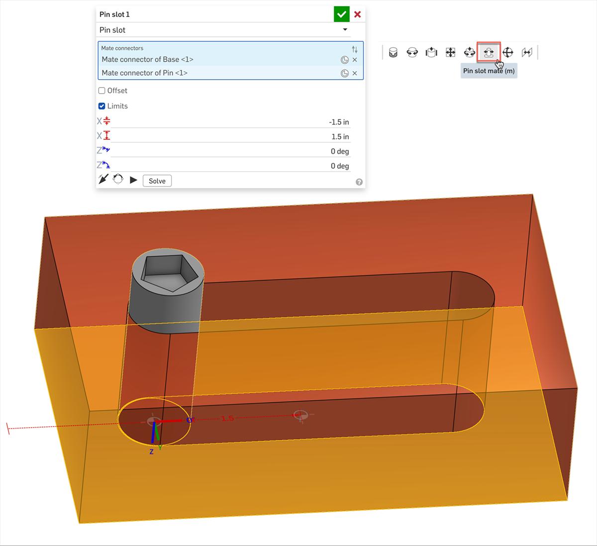
If there is a slot that is not parallel to one of the axes, you might simply need to realign your mate connector's secondary axis.
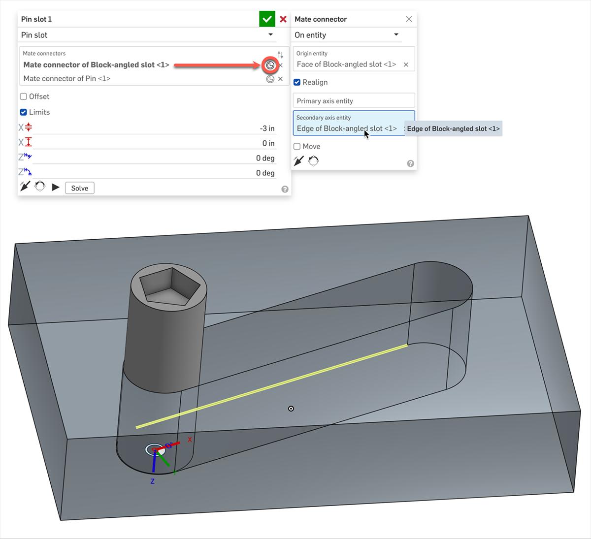
You can achieve the same result using a sketch combined with a tangent mate, which also works on a non-linear slot.
This Tech Tip shows you this workflow as well as a sliding mechanism following a 3D curve.
Using Parts, Sketches, and a Non-Linear Curve for a Sliding Motion
To realize a motion along a non-linear curve, add the Slider Plate, Pin, and their sketches to the Assembly. Group or mate each of the parts to their own sketch, including a Planar Mate to ensure that the Pin remains upright. Then use the Pin’s center point (sketch) as a vertex for a Tangent Mate with the Slot curve.
Using a 3D Curve to Define a Sliding Motion
In the last and most complex example, we are using a Tangent Mate to have a Pin slide along a 3D curve. Here we are using a cylindrical body so we will also have a Cylindrical Mate.
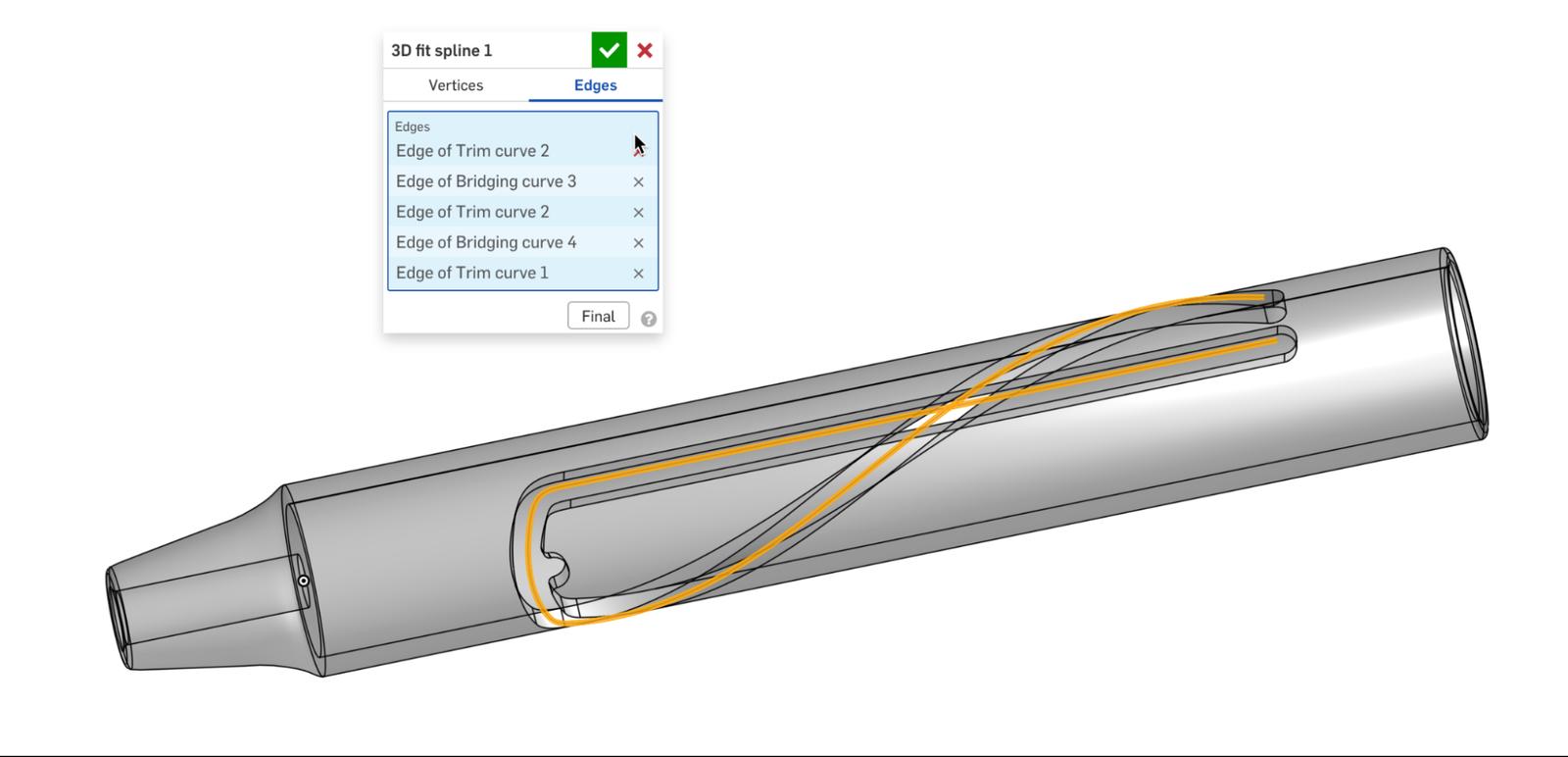
Extra Tip: Use a 3D fit spline to combine multiple segments of curves or sketches into one single 3D curve. To add a spline or curve to an Assembly create a Composite Part using the curve.
Learn more about different Mates in the Onshape Help documentation or from the following resources:
- Learning Center Article: Mating Basics
- Tech Tip: How to Align Slot Mates in Onshape
- Tech Tip: How to Sketch Slots
Watch the video below to see this Tech Tip’s easy-to-follow workflow. Then, look at the setup yourself in the public document Tech Tip: Advanced mating techniques.
Connect with other Onshape users to learn new tips and tricks, and to discuss the latest on design and 3D modeling.
The Onshape Learning Center
Take self-paced courses, get technical briefings, or sign up for an instructor-led training session.
Latest Content
- Blog
- Becoming an Expert
- Assemblies
- Simulation
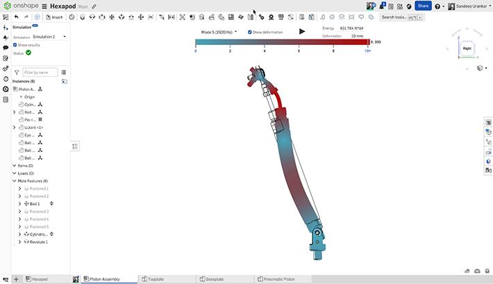
Mastering Kinematics: A Deeper Dive into Onshape Assemblies, Mates, and Simulation
12.11.2025 learn more
- Blog
- Evaluating Onshape
- Learning Center
AI in CAD: How Onshape Makes Intelligence Part of Your Daily Workflow
12.10.2025 learn more
- Blog
- Evaluating Onshape
- Assemblies
- Drawings
- Features
- Parts
- Sketches
- Branching & Merging
- Release Management
- Documents
- Collaboration
Onshape Explained: 17 Features That Define Cloud-Native CAD
12.05.2025 learn more


