
7:09
Well, another quarter is behind us and it’s time to look back at some highlights of what was introduced to the Onshape platform.
The R&D team steadily rolled out a staggering number of improvements to both the core modeling and drawing environments. But what is truly impressive is how much better of an overall experience we believe you will have due to these changes and improvements.
The latest updates provide users with tools that help improve existing design workflows and deliver new tools, such as support for 3D lidar (Light Detection and Ranging) scanning devices and the mixed modeling environment, to enable workflows that were previously not possible.
There were many updates this past quarter, but let’s take a closer look at some key highlights in the following areas:
- Core Modeling and Drawing
- Drawing Environment
- General Usability and Experience
- Mobile/iOS Improvements
- Render Studio
Core Modeling and Drawing
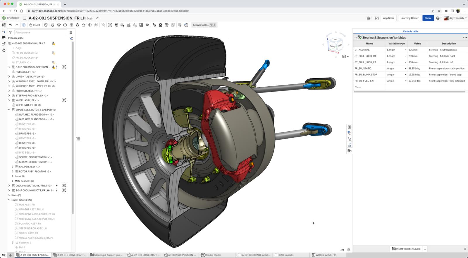
Variable Studios (Global Variables): One of the most consistently requested features over the last several years has been global variables, specifically variables that can be shared between Part Studios. Variable Studio is the tool that enables users to create global variables, expanding on the already powerful Part Studio Variables. Addressing another highly requested feature, these variables can be used in both Part Studios and Assemblies, as well as being able to be used across Documents and versioned. In the example shown below, there are variables saved that are calculated fields for the extent of the suspension travel and overall steering range of motion. Those variables are shared between the Documents used to design the suspension components themselves, the cooling ducts for the brake caliper and rotor which must clear the suspension components, etc.
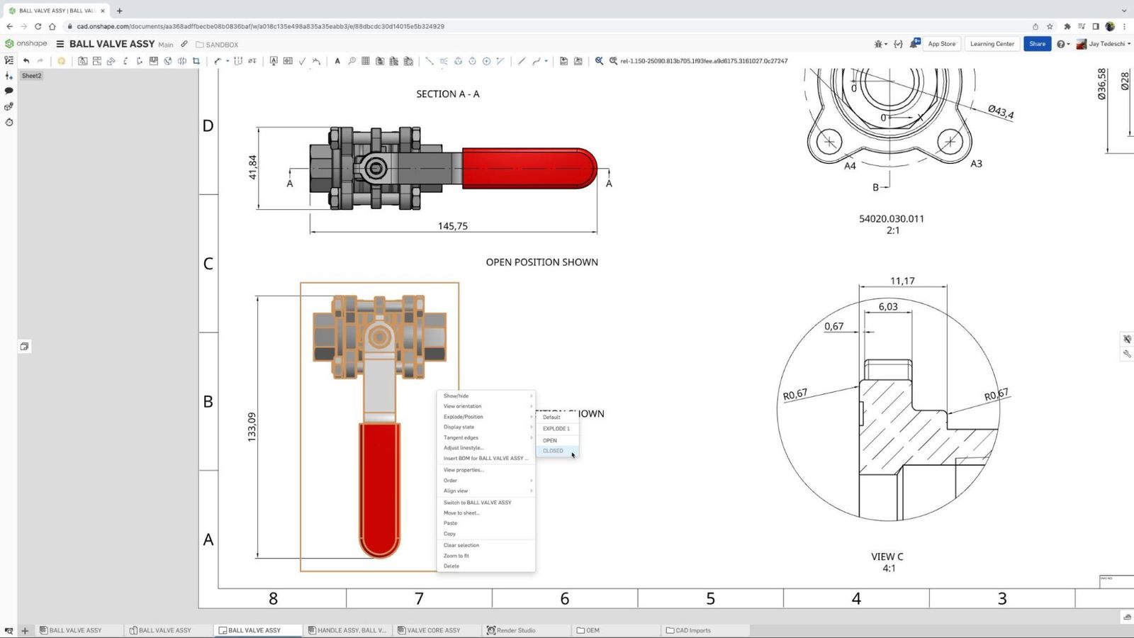
Named Positions Enhancements: Named Positions are receiving a major upgrade with a new UI. Named Positions have moved from the Assembly toolbar to the right-side panel. You can now add mate degrees of freedom to the new Named Positions table and use the Named Positions edit mode to drive assembly parts and mate positions. They can also be used in the drawing environment to configure the position of components in assembly drawing views.
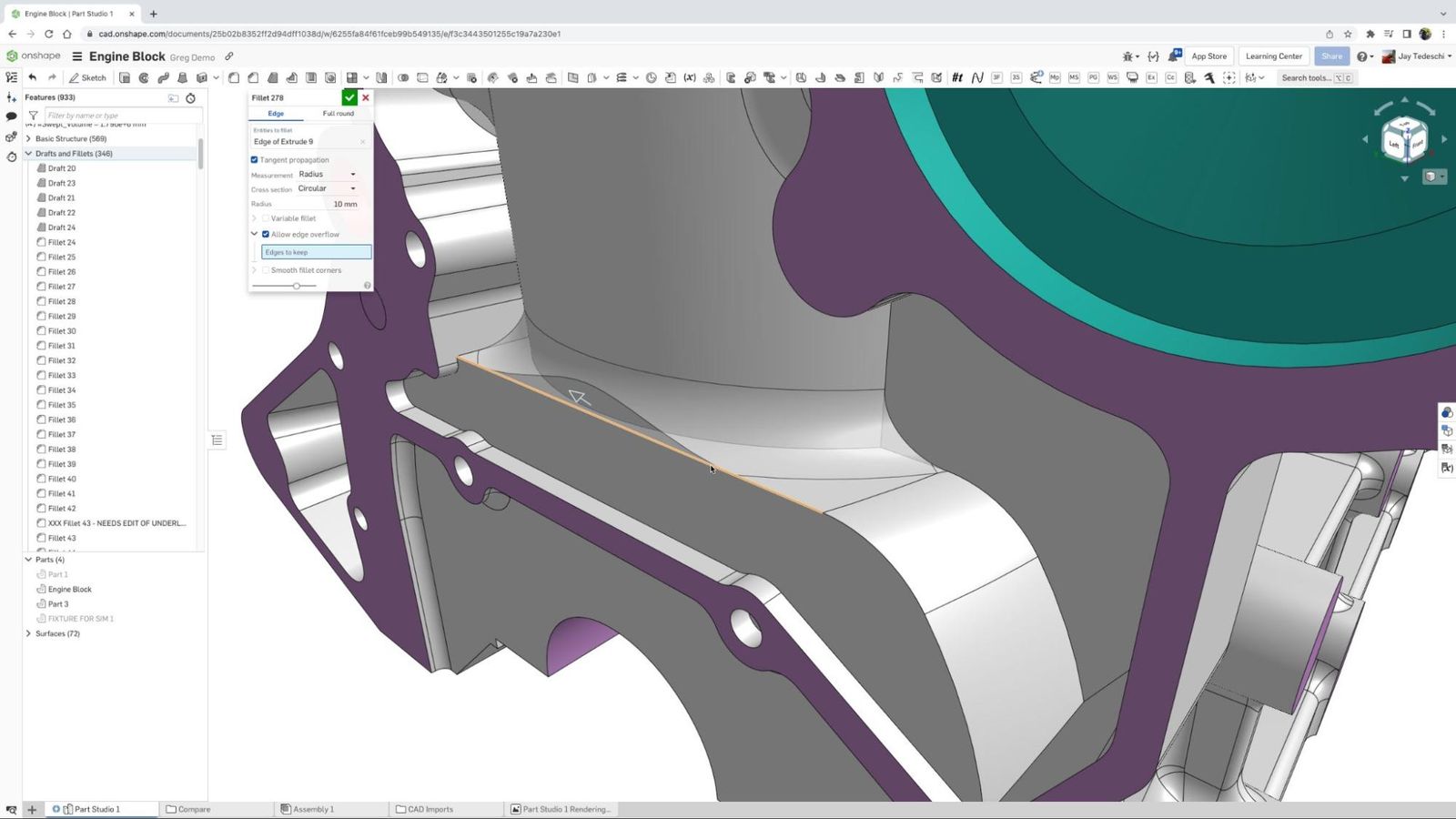
Fillet Improvements: The Fillet feature has two new options – "Edges to Keep" and "Smooth Fillet Corners" – that provide greater control and more flexibility over the implementation of fillets and their effect on surrounding geometry.
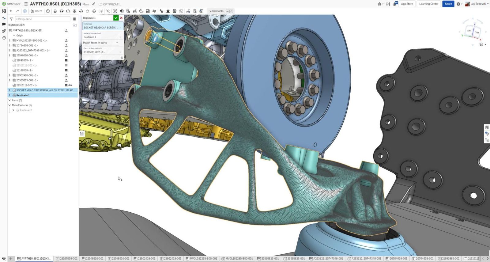
Mixed Modeling: The use of mesh data, from a variety of sources, but most often the output of high precision scans, is becoming more prevalent in today’s design processes. With the introduction of Onshape’s Mixed Modeling toolset, STL and OBJ files are now considered to be fully-fledged parts and/or surfaces rather than a mesh and are indicated as such in the browser Parts List. These can now be used in Part Studios, Assemblies and Drawings just as any other part or surface.
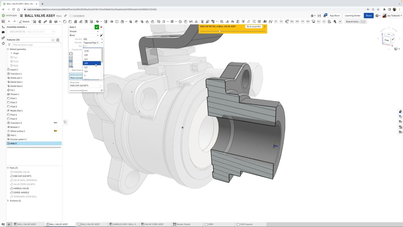
Tapered Pipe Holes and Call Outs: For design work on components specific to those systems used to transport liquids, gases, steam, and/or hydraulic fluid, pipe threads are required for compliance with various industry standards, e.g., ASME. Onshape’s new Tapered Pipe Threads tool ensures that your parts and drawings are compliant with those standards.
Drawing Environment
It’s safe to say that the two areas that saw the greatest number of improvements over the last several months were core modeling and drawings. In addition to some of the more high-profile additions/improvements over that period, changes were also made to add support for auto-generated centerlines, version referencing, projected views, cutlist tables, and edits to holes and other callouts on the field of the drawing.
Three of the biggest updates were the focused attention on access to the Style Panel for a number of drawing elements, greater access and ease of use with regards to hiding or showing components in drawing views, and automatic extension line breaks and the ease with which those breaks can be edited.
Here are more details on the top three updates in this category.
Style Panel Updates: Style Panels are now available, which enable quicker and easier access for changing the appearance of the following drawing field items:
- Geometric Tolerances & Notes
- Bend Notes
- Weld Symbols
- Datums
- Hole Callouts
- Callouts and Surface Finish symbols
Show/Hide Parts in Drawing Views: To show or hide parts in assembly drawing views, there is a new option – "Show/Hide Parts..." – in the Context Menu under Show/Hide. This opens a dialog window and the parts to be hidden can be selected from the Drawing view. To show hidden parts again, open the dialog again and simply delete the parts that should be visible from the selection list.
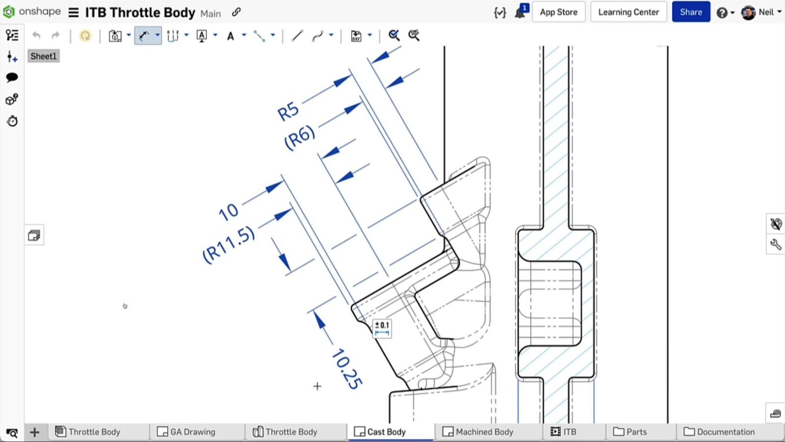
Break Extension Lines: When dimensions overlap, Onshape now automatically breaks extension lines to make Drawings clearer and easier to read. Breaks can be overridden from the Context Menu or the Styles panel.
General Usability and Experience
Similar to the changes to the drawing environment, the updates that focused on improving general usability and overall experience were numerous. These included the much-requested ability to search for Documents based on user criteria, and, following in the theme of making documents easier to locate, search filters were added to Feature Studios.
Similar to the drawing environment summation, if I had to pick the most potentially impactful updates in this area these would top the list:
3MF Import and Export: You can now import 3MF geometry into Onshape. This can be very useful if you want to maintain multiple mesh parts and appearances when working with mesh geometry. Additionally, the export of assemblies or parts in a 3MF format is supported as well.
3MF, also called 3D Manufacturing Format, is a file format developed specifically for additive manufacturing. It offers advantages over both OBJ and STL files, such as smaller file size and better quality, as well as having the ability to save face color information with 3MF.
Continuous “Drag-To-Trim”: With the Trim tool active, users can now drag a continuous trim line to cut back sketch entities to their nearest point of intersection with surrounding sketch geometry.
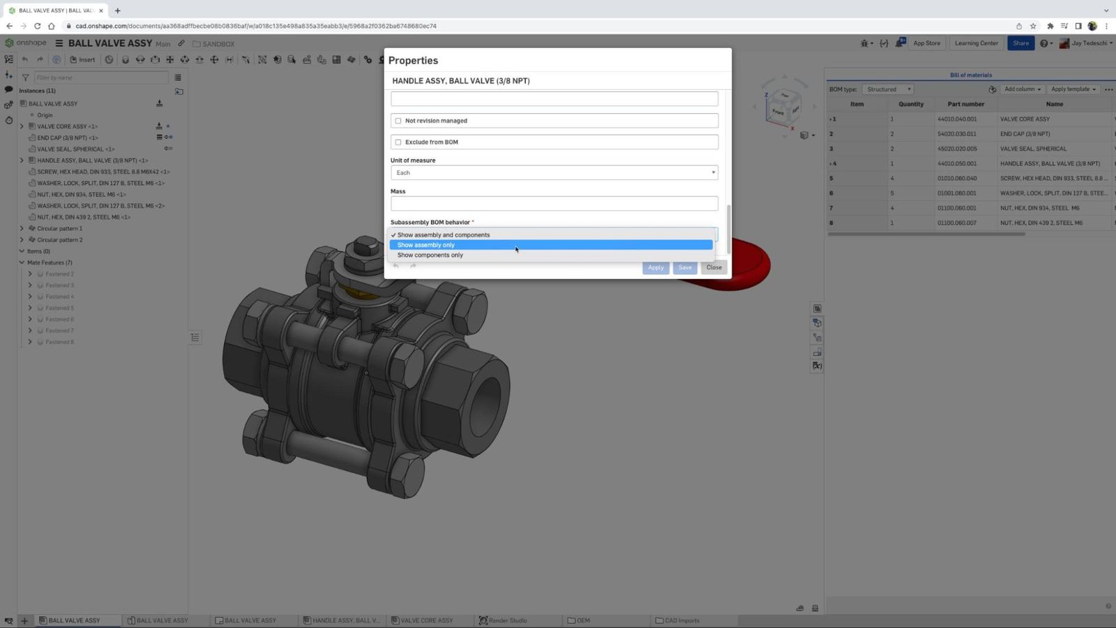
Subassembly BOM Display Options: You can now independently control how a specific subassembly appears within a higher-level Bill of Materials. You may display the subassembly with its parts indented below (the default display), show ONLY the subassembly, or hide the subassembly and "promote" its parts to the next level of the BOM.
Mobile/iOS Improvements
Lidar 3D Scanning Support with Automatic Mesh: Onshape is proud to introduce a novel way to 3D scan and measure objects using Onshape Mobile on iOS, powered by Vuforia Engine. Inside of an open Onshape Document, users can initiate a lidar 3D scan. Just pick up your iPad, walk around your target and notice how you will see the scan layered over the physical object in augmented reality, in real time!
Onshape will generate a data file as well as a new Part Studio in the Document with a composite mesh. This feature is meant for larger objects or area scans. This is a novel approach to reducing the complexity and cost of getting 3D scan data into CAD and doing it faster than ever before.
Render Studio
Options and Camera Settings Toolbar Icons: The camera options and settings tools have been repositioned in the UI for easier access. You can now open up a position and rotation menu in the view cube dropdown.
Select by Appearance/Copy & Paste by Appearance: Right-clicking on an appearance opens the Context Menu with a new "Select All Elements" option. This automatically selects all elements this appearance is assigned to and highlights them in the graphics area and in the Scene graph. Following the same workflow, users can now copy and paste Appearances directly in the graphics area. A right-click on an element gives users the option to copy this appearance. Another right-click on an element opens the Context Menu and allows pasting with the usual methods.
Select Exploded Assembly Views from within Render Studio: Exploded views for better representation of assemblies that already exist in Onshape Assemblies. With this update, the exploded views of Onshape Assemblies can also be used to create scenes in Render Studio.
Enhancing the Onshape Experience
The changes you see here are the result of the Onshape development team incorporating ideas and feedback from our community of over 2 million users. This “conversation” in places like the Onshape Forum and during our interactive webinars, provides you, the customer, the opportunity to be heard, and enables us to address your most pressing needs.
We look forward to continuing these conversations with you and expanding the breadth and capabilities of Onshape in the months ahead!
What’s New in Onshape?
Learn more about the latest improvements to Onshape functionality and tools.
Latest Content

- Case Study
- Automotive & Transportation
Zero Crashes, Limitless Collaboration, One Connected Workflow With Cloud-Native Onshape
12.04.2025 learn more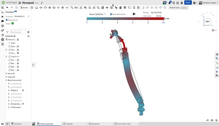
- Blog
- Becoming an Expert
- Assemblies
- Simulation
Mastering Kinematics: A Deeper Dive into Onshape Assemblies, Mates, and Simulation
12.11.2025 learn more
- Blog
- Evaluating Onshape
- Learning Center
AI in CAD: How Onshape Makes Intelligence Part of Your Daily Workflow
12.10.2025 learn more
- Blog
- Evaluating Onshape
- Assemblies
- Drawings
- Features
- Parts
- Sketches
- Branching & Merging
- Release Management
- Documents
- Collaboration
Onshape Explained: 17 Features That Define Cloud-Native CAD
12.05.2025 learn more


