1:36
Certain features do not necessarily need to be modeled with 100% accuracy when building 3D parts. External threads are one such example. Building these threads in 3D is unnecessary in most cases and can impact performance, particularly in large assemblies. Adding thread callouts to the drawing is usually sufficient to assist the machinist in manufacturing.
The External Thread Feature
While this water bottle's thread is likely to be molded as part of the plastic injection molding process, it still demonstrates the External thread feature.
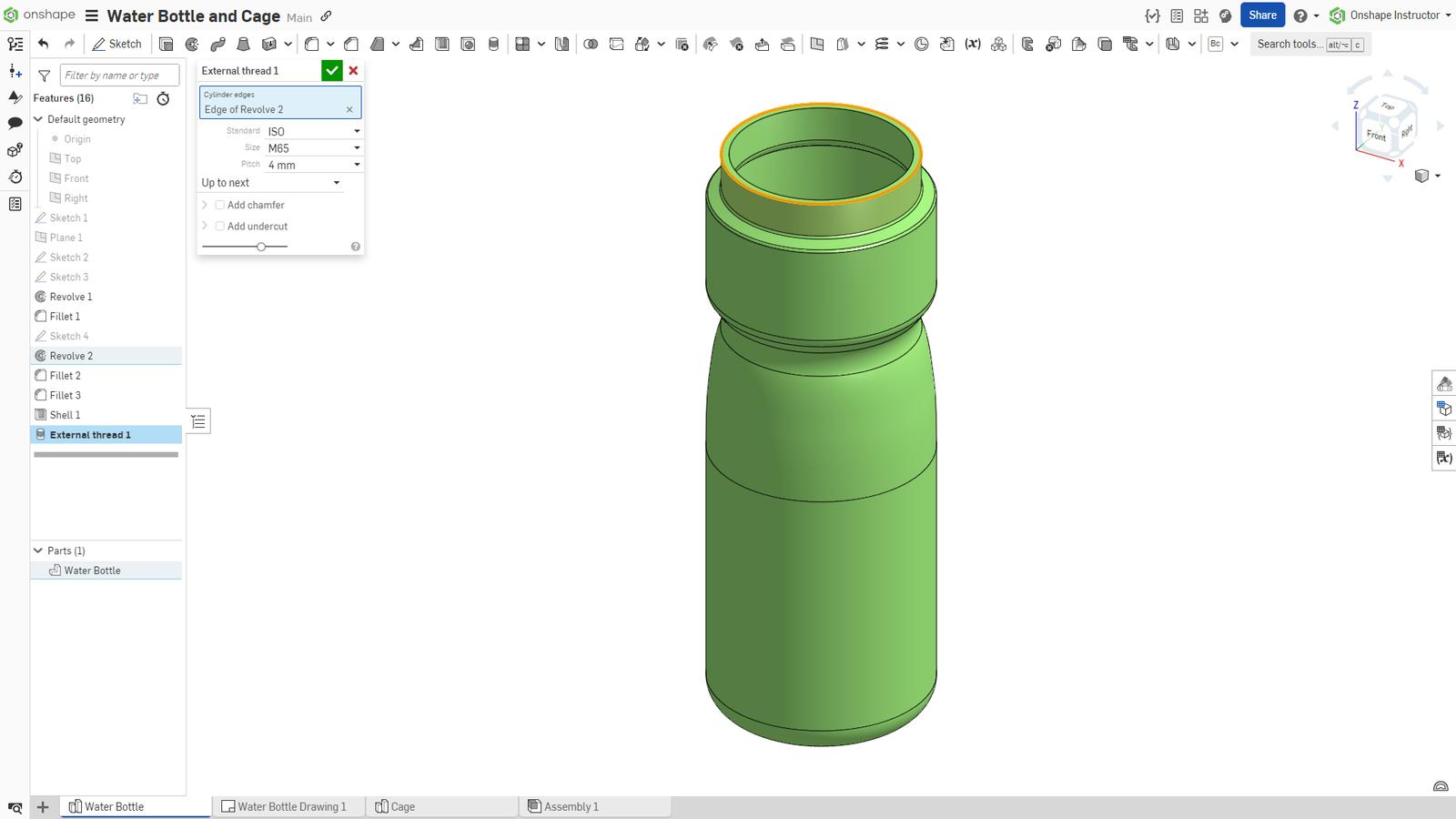
Start a new External thread feature from the Features toolbar. Select the edge or edges of a shaft or other convex cylindrical face. To add multiple external threads, select multiple edges of the same size.
Then, define the Standard, Size, and Thread pitch.
Set the End type to Blind or Up to next. Define the total thread depth for a Blind End type. Up to next continues the thread up to the termination of the cylindrical face.
External Thread Options
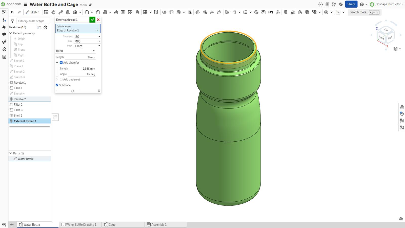
Optionally, add a chamfer at the top of the thread. Define the chamfer’s Length and Angle.
Optionally, add an undercut at the bottom. The Diameter and Length default to values based on the thread and pitch, but can be modified.
Enable the Split face option to help visualize the total depth of the thread.
Threads on Drawings
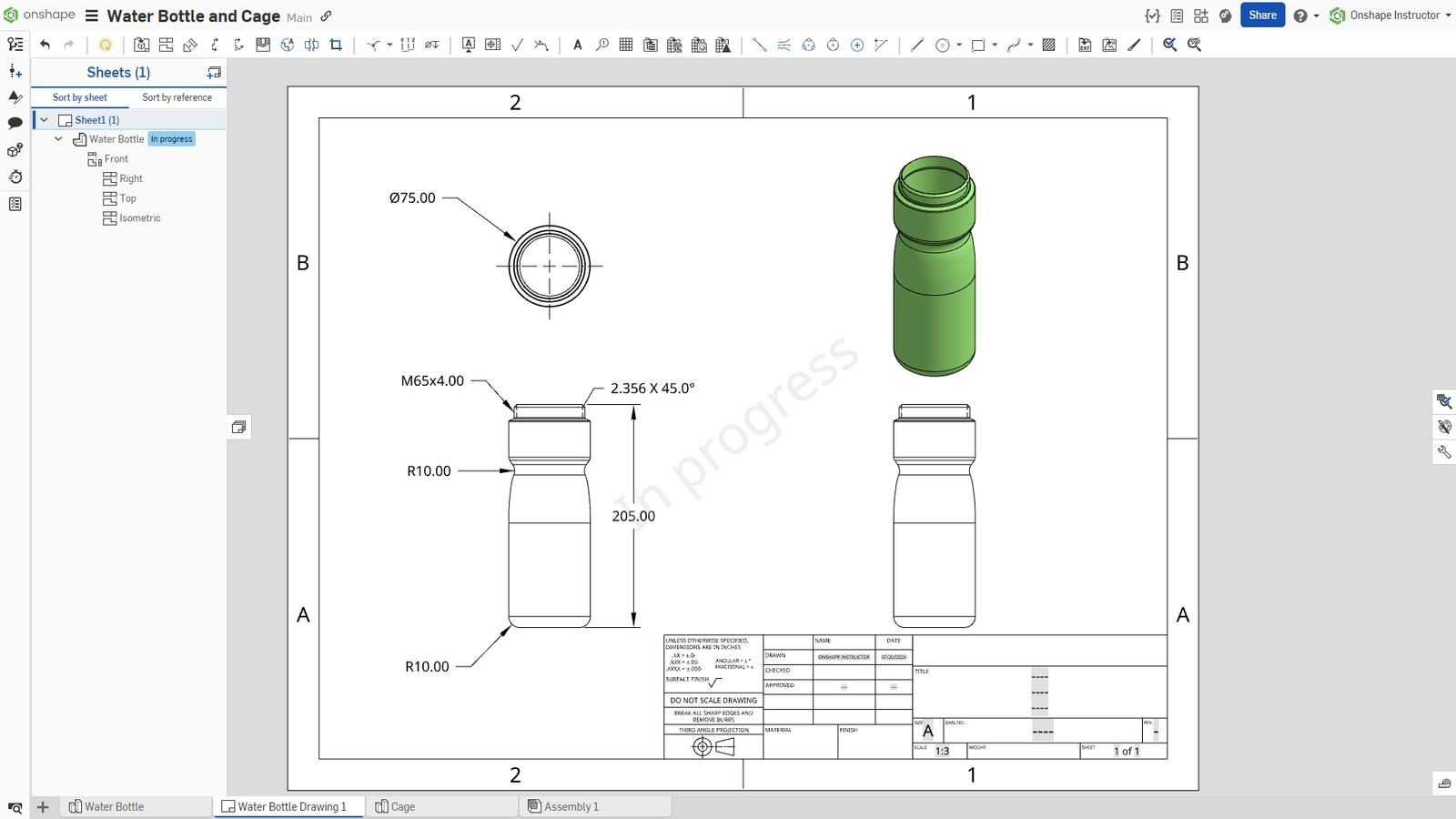
In the drawing, you can see the thread with phantom lines inside the shaft. Start a new Hole/Thread callout, and click on one of the external edges of the shaft or cylindrical face. The split line indicates the termination of the thread whether or not you added it during the thread's creation. However, if you want to add a dimension for the thread depth, ensure the Split face option is enabled.
Watch the video below for this Tech Tip in action:
Interested in learning more Onshape Tech Tips? You can review the most recent technical blogs here.
Friends Don’t Let Friends Use Old CAD!
Know a colleague who could benefit from our cloud-native, fully-featured collaborative design platform?
Latest Content
- Blog
- Becoming an Expert
- Assemblies
- Simulation
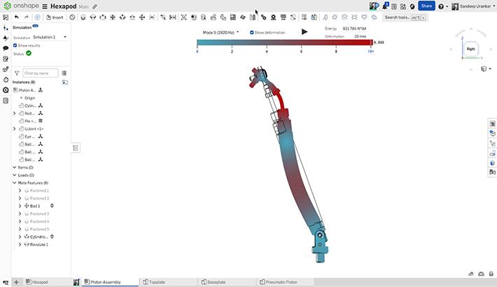
Mastering Kinematics: A Deeper Dive into Onshape Assemblies, Mates, and Simulation
12.11.2025 learn more
- Blog
- Evaluating Onshape
- Learning Center
AI in CAD: How Onshape Makes Intelligence Part of Your Daily Workflow
12.10.2025 learn more
- Blog
- Evaluating Onshape
- Assemblies
- Drawings
- Features
- Parts
- Sketches
- Branching & Merging
- Release Management
- Documents
- Collaboration
Onshape Explained: 17 Features That Define Cloud-Native CAD
12.05.2025 learn more


