Mold design is one of the most complex aspects of product design. Not only are the part geometries challenging, but the timeline to get jobs quoted and manufactured are tight. OEM design companies sending designs to contract mold designers is typically the last stage of the design cycle, and “tooling up” can be some of the most expensive parts of the project.
Luckily, there are some mistakes that part designers and mold makers can avoid to reduce time and cost.
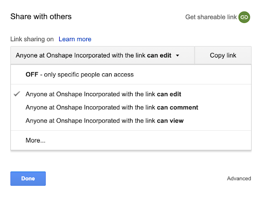
- Share Early and Often – The earlier a design can be shared from a part designer to a mold maker the better. And when I say “share,” I don't mean email files around. Use a system that makes it easy for the part designer and the mold maker to engage with each other so that each party knows which revision of the part is being considered. Many companies are embracing cloud-based file transfer, using services like Google Drive and Dropbox. And newer CAD platforms like Onshape even provide secure access to CAD models without the need to export and manage copies of large CAD files.

A share screen from Google Drive, which allows granular access to be provided to a document. This is better than sending an email. File copies in an inbox or outbox are disconnected and important updates to information can be missed in an email-based approach.
- Determine a Compatible File Format – When getting models in the hands of a mold maker, make sure it is in the best file format for them to work with. There are numerous CAD, CAM and Simulation systems on the market, so it is difficult to know exactly what the best file type is to exchange. Ask the mold maker what format works best for them. Typically a neutral file format like STEP is best. Formats that are also good to share are Parasolid (X_T) and ACIS (SAT) file types, as most systems will import and export them. When sending native formats, it is hard to know exactly which CAD system version will work. For example, if you have a copy of SOLIDWORKS 2016 and receive a SOLIDWORKS 2018 model file, you are out of luck.
- Be Clear When Submitting a Request for Quote (RFQ) – Make sure that you have considered the material, how many parts are going to be made (this helps in estimating mold life and mold material selection), and what your timeline is to get first articles and production parts. Create a standard form that you can use to send to your mold suppliers.
- Get in the Habit of Ad-Hoc Design Reviews – The more you know about the design requirements, the higher probability you have of reducing mold trials. Many modern mold design companies are using web conferencing tools such as Zoom, Webex, LogMeIn, etc., to have design reviews, share screens and record notes on important aspects of the design. Other forward-thinking companies are using comment-and-markup tools like Adobe PDF to provide an audit log of proposed modifications to make parts easier to produce. Furthermore, design platforms that provide built-in comment tools to markup a design will accelerate the mold design process.

Two users in the same document seeing live updates to the design. The part designer on the left is viewing the position of the moldmaker’s screen on the right using the follow mode.
- Run Design for Manufacturability Checks – Run these checks on the data that you get from part designers. Far too often, designs come in that need to be modified. These include the addition of draft angles or displays of where parting lines should be placed. Make sure that your CAD-viewing platform has the ability to check for Draft. Seeing this in a colored plot on the screen makes it clear that the part can be made.
- Check for Undercuts When Quoting Mold Designs – These features add more complexity, time and cost in the production of a mold.

Draft analysis and undercut detection in a view-only document. To open the design, follow this link and turn on draft analysis under the view cube in the upper right hand corner.
- Spend Time Collaborating on Material Selection – This can have a huge impact on cost, performance, and even more importantly on the geometry of the mold. Shrinkage rates for the plastic need to be considered in the design of the mold and depending upon the geometry, the shrinkage could be anisotropic, meaning it shrinks at a different rate in the X, Y and Z axis. Make sure that you can easily apply this to your designs in the CAD system of your choice.

Section View to measure wall thickness and Bill of Materials Panel to see material selection. To open the design to this tab, follow this link and hit the "BOM" button to view the material selection.

Part shrinkage considerations shown by comparing the original versus the proposed change and a discussion with the part designer and the mold maker in the Comment panel.
- Create Surfaces that Represent the Shutoffs – The shutoffs are where metal-to-metal contact occurs in the parting line. This will make it easy to separate the mold into several pieces at the appropriate time.

A design branch showing the surfacing required to accomplish a proper mold split. To see this branch, follow this link.
- Account for Overburn on Parts that are Created with Graphite Electrodes – Overburn is typical on highly detailed or small parts for inserts and side cores. Creating offset surfaces is easily accomplished using direct modeling techniques found in some CAD tools.

A design branch showing the overburn offset for the surfaces on the side core. To see this branch, follow this link.
- Set Revision Stamps and Part Numbers – Set them on your customer’s part data as well as your mold assemblies to keep track of your manufacturing process. This ensures that you are manufacturing to the correct version of the customer part. A system that can automatically label part and assembly versions with the associated inspection drawings will reduce your risk of making the wrong part.

A release candidate screen showing a change order for parts and assemblies that are going to initial revision “A” with automatic part numbers. Note that there are several users who are involved in approving the change order.
Modern design platforms are making it easier than ever get production parts manufactured rapidly with high quality. Think about using SaaS-based applications for data sharing such as Google Drive and Dropbox for instant file sharing. Or consider using a modern design-centric SaaS platform such as Onshape that includes CAD (for part and mold design), data management (for version and revision control), collaboration (for design reviews), and Bill of Materials management (for understating part counts, costs and material specifications).


