I’m an industrial designer by training with a strong engineering focus. Of late, I’ve been cast in the role of studio engineer, moving freely between both circles. The world I live in revolves a lot around giving form to objects. Some notable examples include infusing the DNA of the iconic KitchenAid stand mixer into a new generation of food prep gadgets (toasters, food processors), and helping people with sleep apnea by crafting iterations of CPAP mask geometry for the ResMed AirFit 30 series. I also teach, coach and train students and professionals alike in the use of various 3D digital tools.
As a writer for SolidSmack – and their resident industrial designer – I’ve followed the emergence and growth of Onshape over the years as we’ve reported on the world of 3D design, technology, and product development. I’ve covered stories about Onshape’s Real-Time Deployment and have reviewed its Advanced Modeling Tools. Along the way, I’ve been privy to a lot of industry chatter about Onshape – the good, the bad, and the ugly.
Candidly, within the industrial designer community (both professional and academia), there has been some reluctance to crossover to Onshape. Their perception is that there is a lack of advanced surface modeling tools.
Onshape in the Early Days
In the beginning, Onshape was pretty lean in regards to tools necessary to develop highly organic geometry. I’m talking features considered to be core surface model creation tools such as 3D curve from two projection, diverse spline creation tools, composite curve, sweep along a curve, etc. The absence of these tools and features at Onshape’s 2015 commercial product launch definitely slowed down its traction in the industrial design community. Unfortunately, these shortcomings drew attention away from the many powerful benefits of this new cloud design platform, such as rapid deployment, real-time collaboration, multi-device modeling capability, etc.
My attempts to surface model in the early releases of Onshape caused me to echo similar sentiments.
But a lot has changed recently. I’ve paid close attention to the “What’s New in Onshape” updates every three weeks, particularly in relation to curve and surface creation. I’ve scoured the Onshape Forums for surfacing-related tidbits, and added my two cents along the way. As new tools and workflows continued to come online, I began to get the itch to give Onshape a fresh surface modeling test drive.
After brainstorming products that were good surface modeling candidates, I decided that creating a computer mouse would be a great way to evaluate Onshape’s current capabilities.
In this blog, I’ll share a high-level overview of my modeling process and highlight some of the key Onshape features I used to create the mouse geometry.
My Onshape Evaluation: Key Objectives
Heading into the project, my aim was to determine the following:
- What are Onshape’s available features for constructing complex curve and surface geometry?
- How intuitive are these tools to use and locate within the modeling environment?
- What is the degree of ease or difficulty to achieve a robust and parametric model?
- Is the creation of complex curve and surface geometry straight forward or does it require workarounds?
- To what degree could I analyze the quality of the geometry as it was being created?
- Personally, is Onshape a good alternative choice to SOLIDWORKS for me and my industrial design students? If so, in what ways?
So let’s dive in and take a closer look at some of the Onshape tools and features I used to build my mouse.
Concept Sketch Reference
I gathered reference images of several brands of mice that had sufficiently complex geometry. I chose an asymmetrical style with no line of symmetry to mirror about. The build would require carefully constructing and blending together each region of the mouse.
Notes:
- Reference images of several styles of mice were selected as inspiration.
- Line drawings were created of the relevant orthographic views.
- I used “Create New Sketch > Insert Image” to place reference images on the desired sketch plane.
Curves
A collection of various curve types were used to construct the boundaries that define the overall shape of the mouse:
- A series of 2D sketches were constructed that approximated the shapes from the reference images.
- 3D curves were constructed using the Projected Curve tool.
- The Spline Curve tool was used extensively to build the non-prismatic fluid boundary curves.
Creating Custom Features in Onshape
Custom features can be created using FeatureScript (FS), the same open-source programming language used by Onshape developers to create its native features. For this exercise, custom features were used in combination with native Onshape features to build up and/or modify the curves and surface geometry.
FeatureScript allows you to create your own custom features from scratch or leverage ones written by other Onshape users who share them with the community. For the mouse design, I relied on these user-written features, which you can find by searching within Onshape.
The 3D Point custom feature proved to be especially invaluable for linking my geometry together.
Notes:
- Extrude Vertex was quite useful for quickly developing ruled surfaces used for trimming operations.
- Boolean Plus facilitated some of the complex surface splittings.
Surfaces
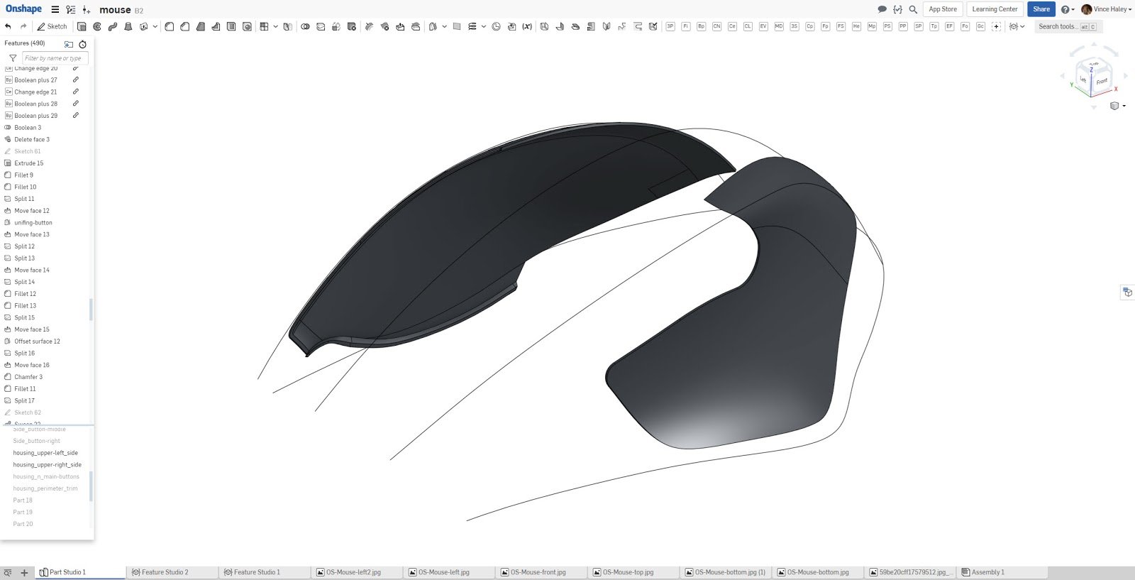
The mouse geometry was built up using a collection of surface patches that were added to each other to form a quilt that defined the overall topology of the mouse.
Notes:
- The Loft and Fill tools were used to form the top and side surfaces.
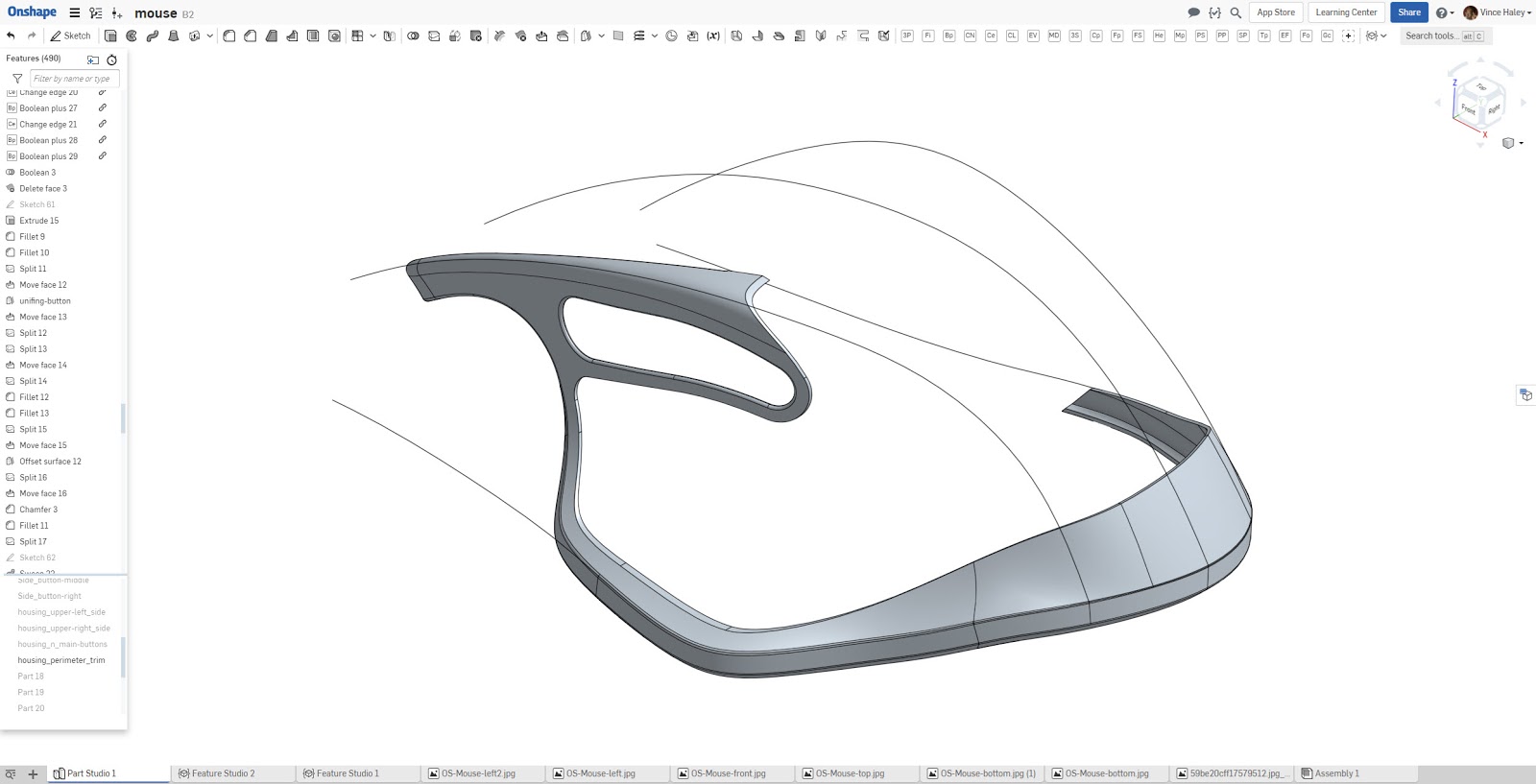
- The lower perimeter and bottom surfaces of the mouse were created using the Sweep and Fill tools.
- Many surfaces were overbuilt and trimmed to achieve desired contours.
- Split Face was used extensively. Delete Face helped clean up and remove the leftover surface patches after split face operations.
The Fill tool was used to create a series of custom surface blends which soften the edges that run along the top left and right shoulders of the mouse. A standard fillet was not suitable in this instance as the lower boundary required the using a portion of the 3D curve that traverses around the perimeter of the mouse. Once all surfaces were constructed, the quilt was converted to solid geometry.
- The Enclose tool was used to form a solid body from the collection of surface bodies.
Parts
The solid was shelled to create a thin-wall part, at which time the geometry was ready to be divided into component part regions. Additional features such as Scroll Wheel and Buttons were constructed as new parts using a combination of Revolved, Swept, and Extruded features.
Notes:
- Ruled surfaces were constructed using the Extrude Vertex FeatureScript and swept along the regions that defined the various component part separations.
- Split Body and Split Face tools were used extensively.
- Move Face was used to create pockets for UI, the on/off switch and recharge port.
- Boolean Combine and Subtract were used to break out components and reattach where necessary.


Model Preparation For Downstream Visualization
With all the geometry completed, I was excited to prep the mouse for export to Keyshot to create some sweet rendering.
Notes:
- The appearance editor was used to designate part breakout and to define regions for CMF exploration.
- Setting unique appearances to faces of a part that has been split is not yet supported. Surface bodies can receive custom appearances, so instead of making surface copies, I opted to fully separate out the components.
Final Takeaways
There’s a mouse in the house! I am pleased to report that Onshape has developed a collection of surface modeling tool enhancements capable of constructing sufficiently complex geometries.
Some concluding thoughts:
- Overall, I found the current UI layout to be straightforward. No one tool was buried too deep to find. The integration of the FeatureScript navigation helped me readily access the key auxiliary tools to complete the model build.
- I had some initial challenges with endpoints of my projected curves, but quickly found an alternative construction method that was robust.
- I did encounter what I would consider a workaround pertaining to edge manipulation of surface patches. I found extending and/or trimming edges cumbersome and in need of enhancement.
- Correcting feature failures at times were a little touch-and-go as Onshape lacks a replace or reroute lost feature tool. However, the model tree flagged problem features and provided fly-out notes indicating the type of failure.
- I leveraged the 3D Point, Extrude Vertex, Boolean Plus, and Change Edge custom features extensively throughout the model to augment the geometry construction.
- With regard to analysis tools, the curvature plot served me well as I laid down my curve network. But when it came to surface mesh flow evaluation, Onshape lacked a tool to visualize how the U and V grid mapped across the surface. However, I discovered when using the Fill tool, I was able to (via a checkbox) toggle on view isocurves. The ability to analyze the quality of the Fill surfaces proved invaluable.
- I appreciated being able to not only view my model in perspective but that this mode remains active while I continue to work. Onshape comes with a fixed camera focal length. It would be a nice addition to have the ability to adjust the focal length.
In summary, I’m glad I put the time and effort into this Onshape surface modeling deep dive and that I can now set my skepticism aside. It’s good to know that the present surface creation feature-set gives me ample room to explore even more difficult geometries. New tools are being released at a good pace and are sure to streamline my workflow even further. To those who are on the fence, I hope this post has answered some of your questions and inspires you to “Give it the old college try!”
If you’d like an even closer look at my mouse design, you can access the full Onshape Document here.


