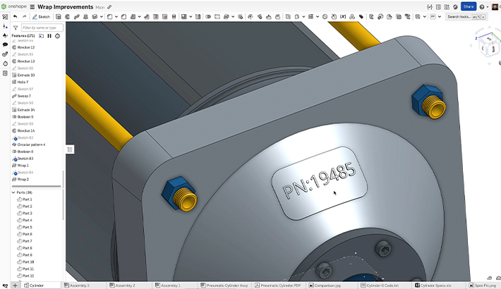
There are many possible ways to work with legacy CAD data and sheet metal parts. The most common way is to use generic file formats like Parasolid (.x_t), STEP, or IGES. See this Tech Tip on Converting Legacy Sheet Metal in Onshape for further information.
Sometimes, though, the only available legacy sheet metal part data is a technical drawing and a flat pattern in DXF file format.
If a fully functional part including the parametric feature tree is required, you need to make some changes and update the DXF file for laser-cutting.
This Tech Tip shows you this workflow.
Adding a DXF to a Sketch
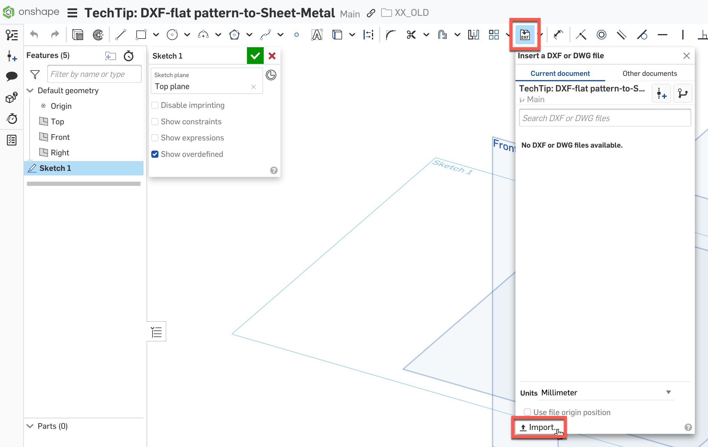
Create a sketch in a new Part Studio, and either import your DXF file or select it from the current or other Document:
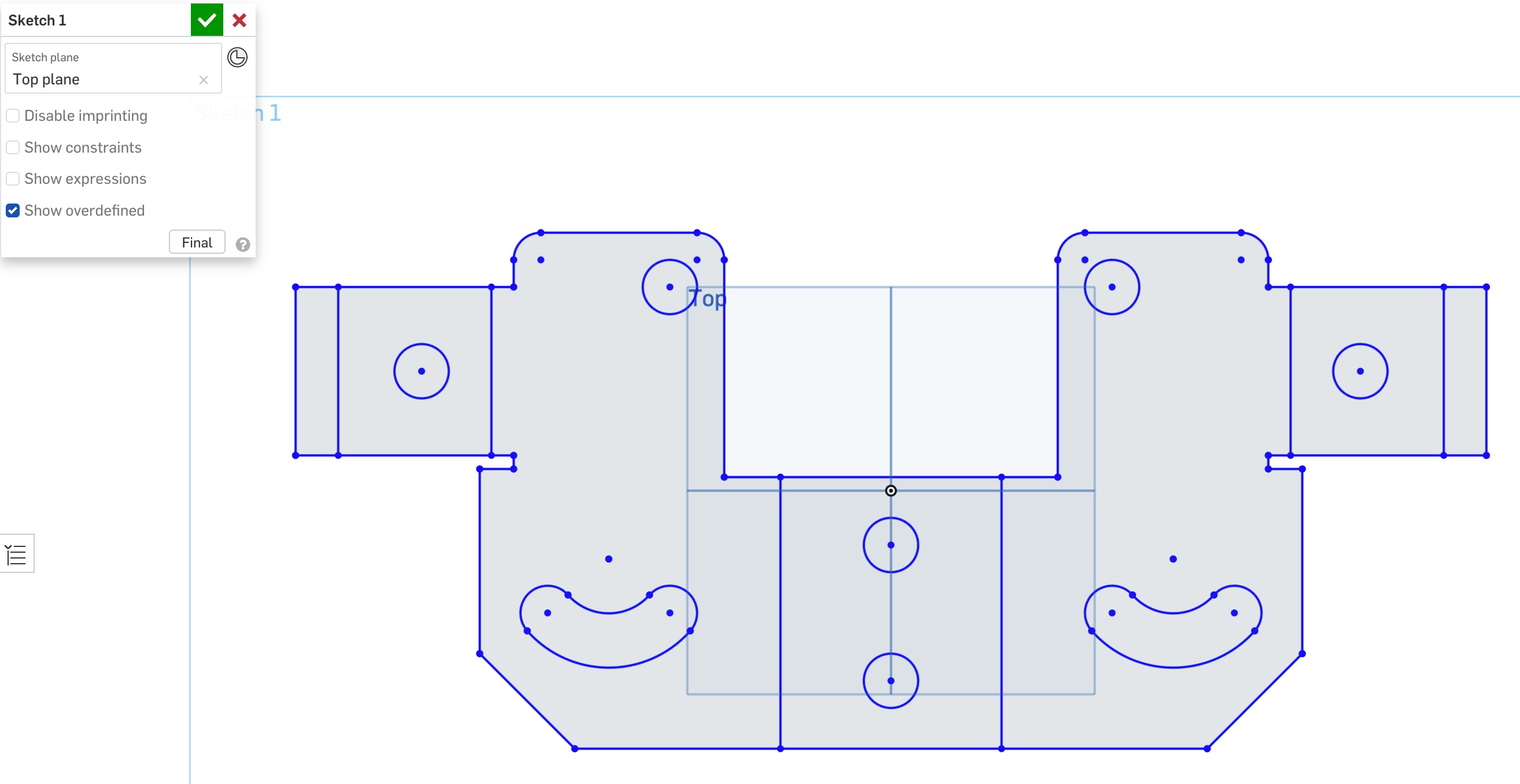
The result is a Flat pattern in an unconstrained sketch. If needed, adjust the sketch to affect the final geometry:
Add Flat Pattern Thickness and Bend It
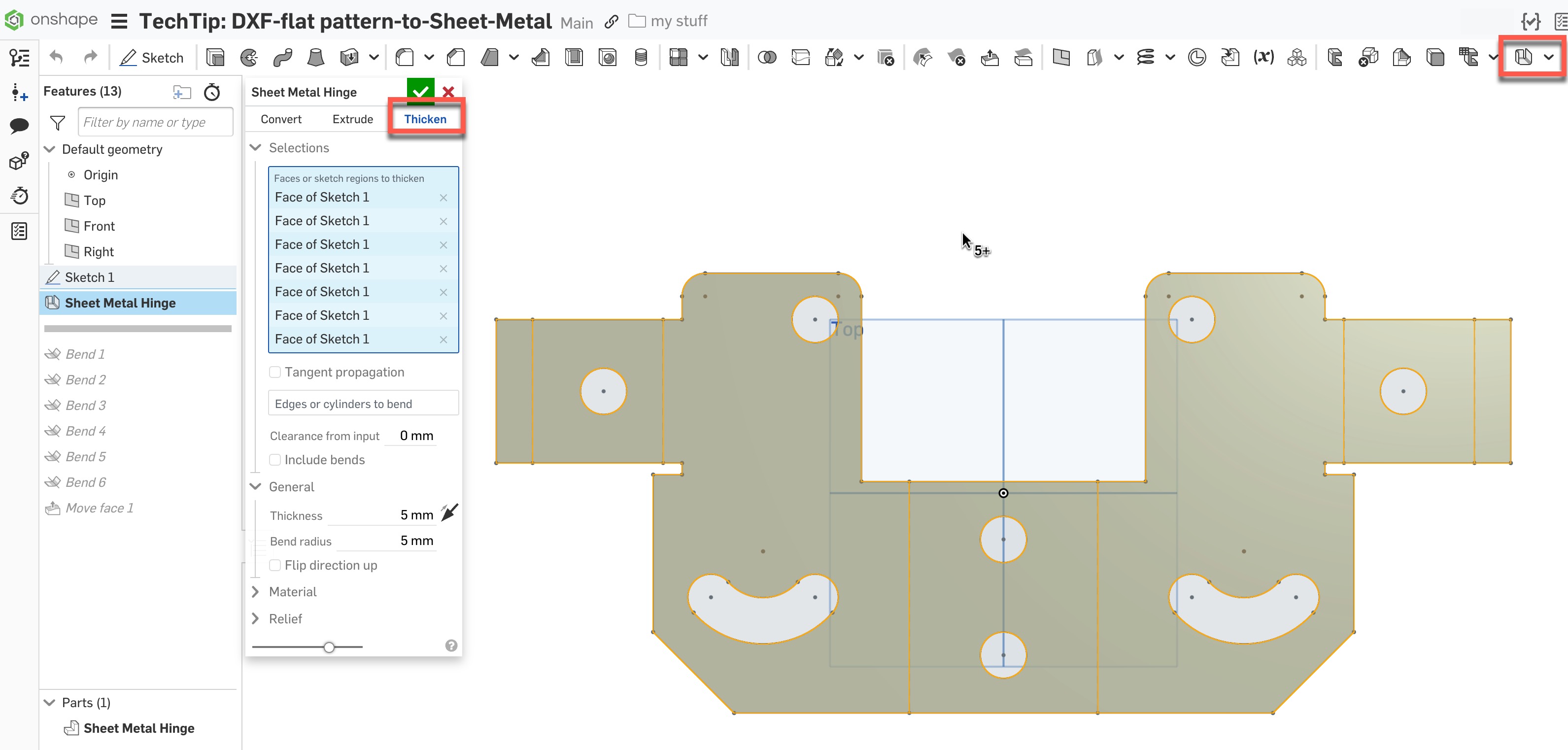
Thicken the desired sketch entities using the Sheet metal model feature. If necessary, leave out certain areas of the sketch (for example, do not use a cutout):
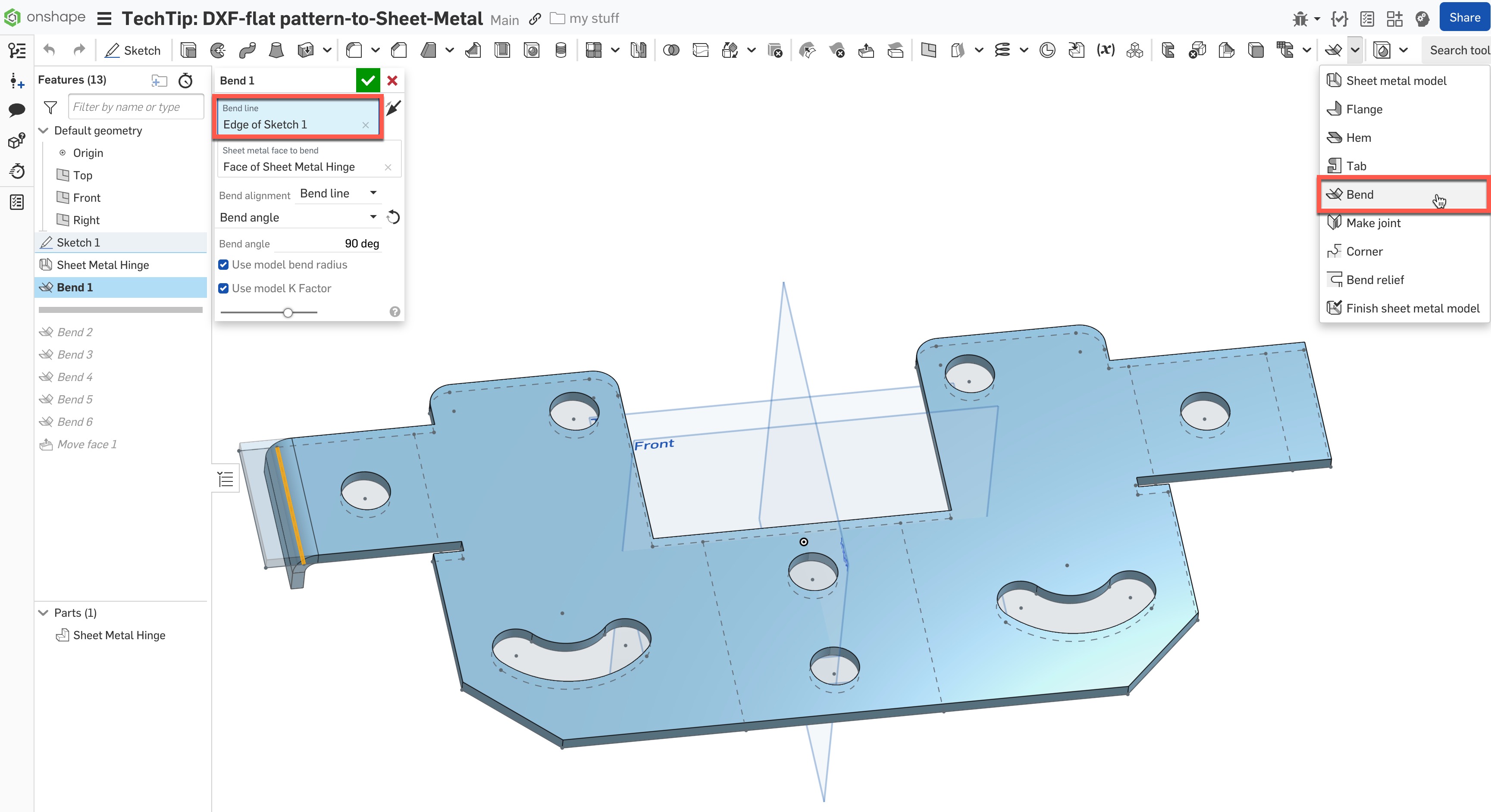
Select the Bend feature and use it for each of the sketch’s bend lines.
Extra Tip: Press Shift+Enter to confirm the command and immediately open the feature again for the next bend line:
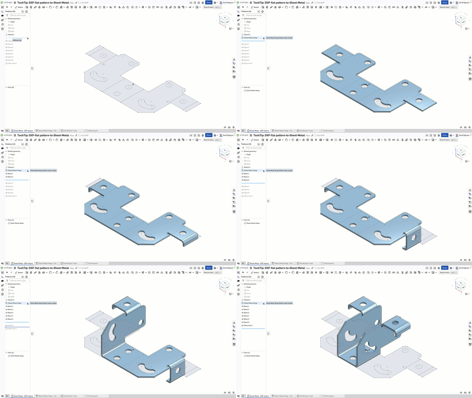
Once the base shape is created, you can use all the available sheet metal features. Additionally, use the Direct Editing tools for quick and easy adjustments.
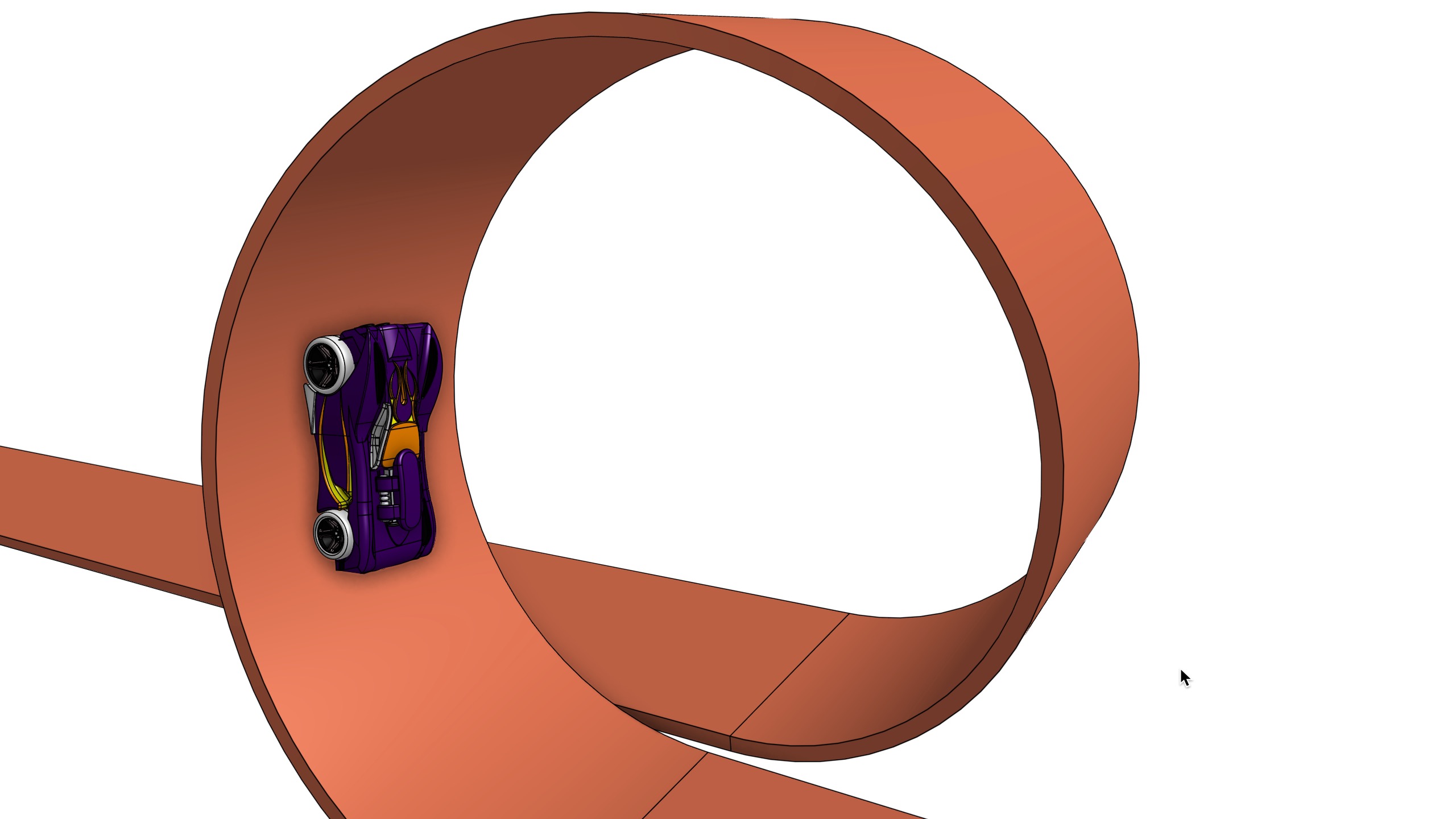
Bonus: Use the Bend Feature to Create Hot Wheels Tracks
Get creative to use the Bend feature for more complex bend operations, for example:
Learn more about the Bend feature in the Onshape Help documentation and these three Tech Tips about working with sheet metal:
Check out the easy-to-follow workflow by watching the video below:
Connect with other Onshape users to learn new tips and tricks, and to discuss the latest on design and 3D modeling.
Join the Onshape User Group Community
Improve design skills and network with industry peers during an upcoming virtual meeting.


